STL to STEP for FEA: Turning a Tooth or Bone Mesh into a Solid for ANSYS, Abaqus and COMSOL
You segmented a tooth from micro-CT in 3D Slicer or Mimics, exported an STL, and opened your FEA package — which wants a solid. ANSYS, Abaqus and COMSOL mesh CAD bodies; a triangle surface is not a body. The usual fix is hours of manual surfacing in reverse-engineering software per model. This guide covers the faster route, what to check before meshing, and when you can skip STEP altogether.
Why FEA packages want STEP, not STL
An STL is only a skin of triangles: no volume, no faces you can select for loads or boundary conditions, no way to control the volume mesh. A STEP solid gives the pre-processor a closed body with real surfaces — it can tetrahedralise the inside, and you can pick faces to fix, load or contact. That is why the standard pipeline is segment → surface mesh → solid (STEP/IGES/Parasolid) → FEA.
Option 1: skip STEP and mesh the STL directly
Worth saying first, because it saves a step when it fits. Some pipelines go straight from a closed, clean surface mesh to a tetrahedral volume mesh — for example with Gmsh or TetGen, or the remeshing tools in medical image software — and import the volume mesh into the solver. This works well when you don’t need to select CAD faces or combine the anatomy with parametric parts. If you need either, or your solver only accepts CAD geometry, you need a solid.
Option 2: rebuild the mesh as a STEP solid
1. Prepare a closed STL
- Watertight is non-negotiable. A solid needs a closed surface. Fill every hole in 3D Slicer, Meshmixer or Blender. Our free STL watertight checker shows holes, non-manifold edges and flipped normals in your browser without uploading the file.
- Smooth lightly. Voxel staircase artefacts from segmentation become real bumps in the fitted surfaces. A light smoothing pass removes them without changing the shape meaningfully.
- One tissue per file. For enamel, dentin, pulp or bone, export each tissue as its own closed STL, convert them separately, then assemble or Boolean the solids in CAD or your pre-processor.
- Keep it under 100 MB; a few hundred thousand triangles is plenty.
2. Reconstruct
Upload the STL on the tooth STL to STEP page. Vertessia fits smooth NURBS surface patches over the whole mesh and, because the mesh is closed, writes a closed solid. The patch size (1 mm by default) controls the trade-off: smaller follows the mesh more closely but produces more faces; larger gives fewer, bigger faces and a lighter file.
3. Check the numbers before you download
The free preview comes with a deviation report measured on your own file: coverage (how much of your mesh the solid covers), mean and 95th-percentile distance from your mesh to the rebuilt surfaces, and a reverse check from the result back to your mesh that flags extra geometry. These are the figures you would quote when describing the geometry in a methods section.
What we measured
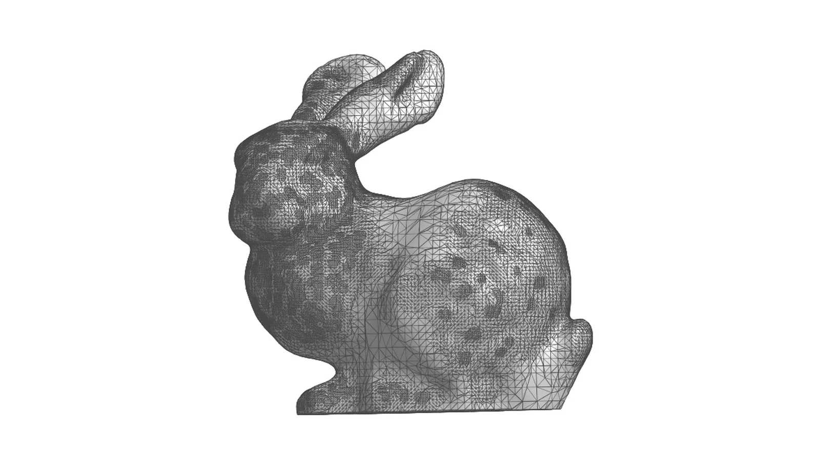
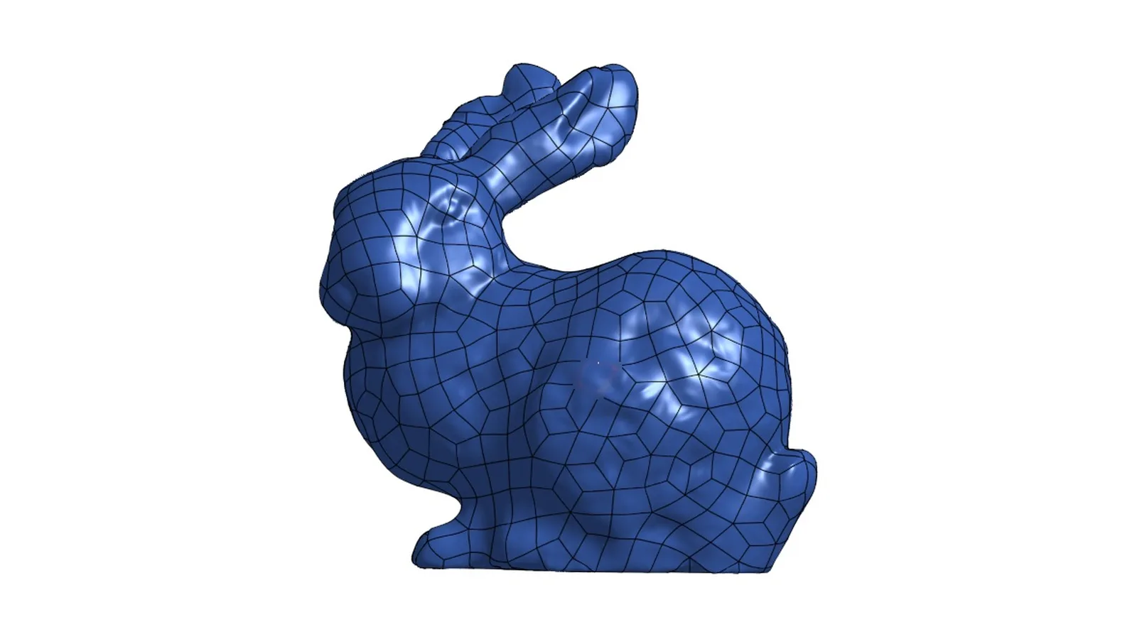
We have not published a tooth-specific benchmark yet. On a closed organic test model — the Stanford bunny, 112,000 triangles — the live engine produced:
| Measure | Result |
|---|---|
| Output | Closed solid, 8,190 NURBS surfaces at 1 mm patches |
| Time | About 1–1.5 minutes |
| Coverage | 100% of the mesh surface |
| Mean deviation | 0.006 mm |
| 95th percentile | 0.019 mm |
Hundreds or thousands of faces: is that a problem for meshing?
A fitted solid has many NURBS faces rather than a handful of clean CAD faces. Most pre-processors mesh this without trouble, but tiny faces can force a finer mesh than you want. Three ways to handle it:
- Use a larger patch size when converting — fewer, larger faces.
- Merge faces in the pre-processor: virtual topology in ANSYS and Abaqus, or composite faces in COMSOL, let the mesher treat many small faces as one.
- Mesh by size, not by face: a global element size with curvature refinement ignores face boundaries on smooth anatomy.
Multi-tissue models
Convert each closed tissue separately and combine them in CAD. Shared interfaces (enamel–dentin, PDL–bone) will not match exactly face-to-face after independent fitting; the usual approach is to Boolean-subtract one solid from its neighbour, or to use bonded/tie contact between them in the solver.
Turn your segmented STL into a solid
Upload a closed tooth, crown or bone STL, check coverage and deviation for free, and pay only if you download the STEP.
Convert a tooth STL →FAQ
Can I import an STL directly into ANSYS or Abaqus for FEA?
You can import it as a surface mesh, but it is not a solid body you can mesh with tetrahedra or select faces on. Either tetrahedralise the closed surface mesh with a volume mesher, or rebuild it as a STEP solid.
Will the STEP be a solid or a surface?
A solid if the uploaded mesh is closed (watertight); an open mesh comes back as a surface model. The free preview shows which one you got before you pay.
How do I report the geometric accuracy?
Use the deviation report: coverage, mean and 95th-percentile distance between your mesh and the rebuilt surfaces, from 20,000 sample points. State that it is a sampled estimate and give the patch size used.
Is this validated for clinical or regulatory work?
No. It is a general-purpose geometry tool, not a medical device, and results are not reviewed by a person. Verify every result yourself.